Your cart is currently empty!
A laser scan gives you millions of points, but a client wants walls, floors, beams and pipes. This guide shows how to model point cloud in Revit step by step: first with Revit’s own tools, then with the ZetaBIM shortcuts that save most of the time.
1. Prepare the scan before you model point cloud in Revit
Revit does not read raw scanner files directly. First, open the scans in Autodesk ReCap, register them and save an indexed project (RCP) with its scan files (RCS). Then, in Revit, use Insert › Point Cloud and choose the RCP.
Tips:
- Place the point cloud with Auto – Origin to Last Placed or by shared coordinates, so later scans line up.
- Keep the RCP and RCS files on a fast local or network drive that every teammate can reach.
2. Set up levels and views
- Create the levels from the scan: cut a section through the building and place levels at the floor surfaces.
- Duplicate a floor plan per level and adjust the View Range so the cut plane sits about 1.2 m above the floor. Walls then show clearly as two lines of points.
- In 3D views, use a section box around the area you model. A small box is faster and easier to read.
- Change the point cloud colors in Visibility/Graphics › Point Clouds. ZetaBIM’s Color Mode PCL does it in one click for every scan in the view.
3. Model walls, doors and windows
In Revit alone: draw each wall along one face, measure its thickness in a section, then choose or create a wall type with that thickness. For openings, measure width, height and sill, then find or create a matching type.
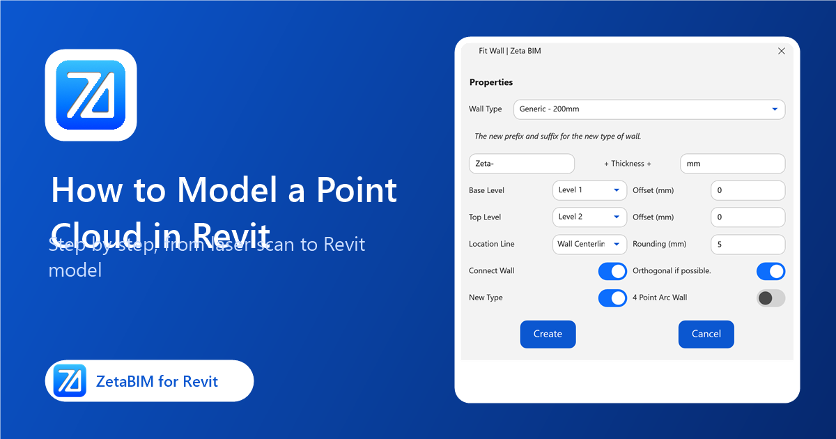
With ZetaBIM: Fit Arch measures the wall when you click its face and creates the type for you. For doors and windows you pick two corners and confirm the size in a preview over the scan. Fit Wall is the plan-view option for walls drawn point by point.
4. Model floors, roofs and terrain
Real slabs and sites are not flat. In Revit you can add shape points with Modify Sub Elements, one by one, typing each height.
With ZetaBIM, Calculate Surface measures the surface on a grid, then Floor By Points, Roof By Points or Topo By Points shape the element to all the points in one step.
5. Model structure and MEP
Columns, beams, pipes and ducts need the right section or diameter. In Revit you measure each one in a section and place it with the matching type.
Fit Structure creates beams and columns at the measured section, and Fit MEP creates pipes, ducts, cable trays and conduits with the fitted size. Afterwards, MEP Corner / MEP Tee connects the runs.
6. Check the model against the scan
Before delivery, compare the model with the point cloud. In Revit you cut sections and look. Deviation colors every point by its distance to the model and lists the elements that are off, so you can fix them and prove the accuracy.
7. Clean up and deliver
- Name types consistently with Rename Types.
- Remove helper data with Cleanup ZetaBIM Data and old CAD with Purge CAD.
- Join elements correctly with Auto Join.
Common mistakes when you model point cloud in Revit
- Modeling in a cluttered 3D view. Crop the view first; picking is faster and more accurate.
- One type per scanned thickness. Round sizes, for example to 5 or 10 mm, so similar elements share a type.
- Skipping QA. A deviation check takes minutes and catches the walls that drifted.
Next steps
See the full Revit point cloud plugin workflow for every ZetaBIM tool in order.
Get ZetaBIM
ZetaBIM is a Revit plugin for scan-to-BIM teams. See the complete guide to the Revit point cloud plugin workflow. Download ZetaBIM to try it, browse more ZetaBIM tutorials, or watch the videos on the ZetaBIM YouTube channel.
About The Author